2 Dice on a Tiny13!
Here is an electronic dice kit based on an Atmel ATtiny13. I love the Tiny13 and one of my first projects was a digital dice. Nothing new, right? But have you seen 2 dice generated on just 5 I/O pins of a microcontroller? I hadn't. But I knew it could be done and this is proof!This project is open source! I'm providing a complete schematic and AVR assembly code. If you would like a PC board and/or a programmed Tiny13 AVR microcontroller chip, I will make them available for a small fee. Believe me, this is one project where hand-wiring on perf board is NOT fun!! I'll also provide complete kits, including a pre-programmed Tiny13 for those interested in the full package with minimum hassle. (Just solder the parts on and Roll!) Please visit the EZdenki.com SHOP or ask for more info on the Contact page.
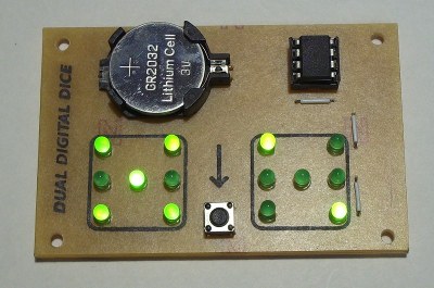
Here is one of my later boards (5cm × 7.5cm).
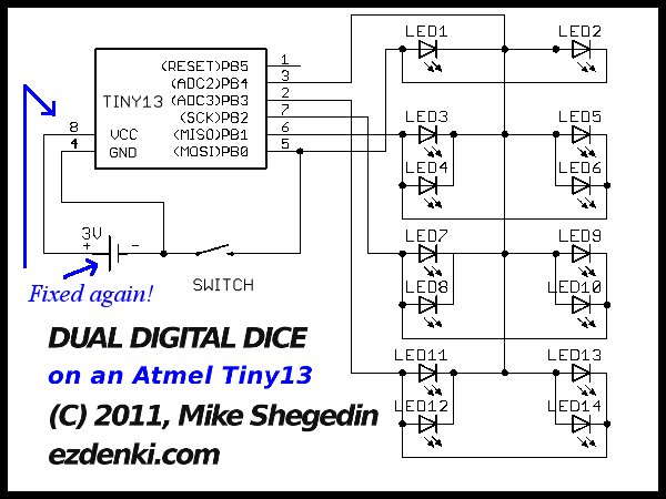
Here is the twice-fixed* schematic. (Click to enlarge.) Do you see how it works?
*Thanks to HACK a DAY and Rob for pointing this out! You guys rock!
Parts List
Here's the short list of things you'll need to build:- 1 Atmel ATtiny13A or ATtiny13V, programmed
- 1 8 Pin IC Socket
- 14 3mm Green LEDs
- 1 Pushbutton Tactile Switch
- 3V Power Source and holder.
- PC Board
- There is some information below regarding programming the Tiny13.
- Other colors and sizes of LEDs would probably work but there will be differences in brightness. What won't work is using a mix of different colors of LEDs in the circuit.
- For power, I like the CR2032 button cell. But a pair of AA or AAA batteries would be fine.
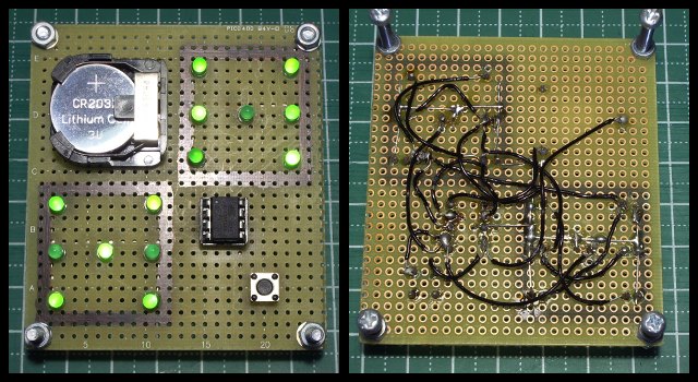
- Regarding the PC board, you would think such a simple circuit would be a breeze to breadboard or wire to perfboard or stripboard. But in spite of the low part count, it's just a pain. I suggest making or purchasing a pre-made PCB.
How It Works:
How can you get any combination of 8 separate dice segments AND a button with just 5 control lines? Read on!Simon Says, "Light your right-center LED!"
Pin 3 on the Tiny13 basically determines the left or right set of LEDs. When pin 3 is low, if any of the other control lines (pins 2, 5, 6, or 7) go high, the corresponding left-side LEDs will light in the desired combination. Likewise, when pin 3 is high, any combination of the right-side LEDs can be chosen. The downside is that left and right side LEDs cannot be lit at the same time. Fortunately we have a super fast microprocessor that can alternately light the left and right sides so it appears that both sides are being lit independently.
Safety in Flashing
An added advantage of switching back and forth between the left and right sides is that the duty cycle of individual LEDs is lower. This means the usual current limiting resistor used with LEDs is not necessary. There's no chance of burning out the LEDs. Normally 5V would easily burn out an LED without a current limiting resistor. But even when this circuit is powered at 5 volts, the LEDs are safe.
No Extra Input Pin? No Problem!
The other trick was to get the button input. While it is possible to use the Reset line on the Tiny13 for I/O, the problem is that once you set it to do so, you are locked out of reprogramming the chip. The only way around it is to have a special fuse resetting device, which most hobbyists do not have. So I avoided using that pin.
As you can see from the schematic, the button is wired to pin 5, which is shared with the center LEDs. In the program, Pin 5 is changed from an output to an input for a very short time to check for the button press, and then it's immediately switched back to an output again.
Haunted LEDs
Perhaps due to the fact that all the LEDs are always connected, when a roll of 6-6 comes up, there is a bit of ghosting in the middle LEDs. I think this is just unavoidable in this circuit and is probably one of the reasons that people say hooking up LEDs in parallel is a no-no. Fortunately the ghosting isn't too bad and if you are actually using the dice to play a game, the effect is easily ignored. The effect will become less obvious when the batteries start to weaken.
Light Bright
Another catch to this particular circuit is that when a center LED is lit, it shines brighter than the other pairs since all the power is going to just one LED. This is especailly evidnet when there is a roll of 1 (center LED only.) I don't think it's a huge deal, but it can be easily remedied with a resister (something around 200Ω or 300Ω works well) between pin 5 on the Tiny13 and positive (anode) side of LED1. As an added bonus, it also practically eliminates the ghosting mentioned above. Dave's kit at SolderSlingers.com incorporates this resistor and I think it's worth considering. In my own design, I was shooting for absolute maximum simplicity and minimum component count, so in early versions, the resistor was left out.
Many AVR Assembly Programming Techniques Covered in the Program Listing
Compiled programs tend to get big fast. That's why I prefer assembly when programming the Tiny13. It allows me to get the most of these inexpensive yet powerful chips. This program listing is loaded with comments and includes techniques such as lookup tables, doing input and output on a single I/O pin, putting the AVR to sleep and waking, and much more. So if you are new to AVR assembly programming and would like to see samples of these techniques, be sure to take a peek at the program listing.
Program Listing
Programming your own AVR
(You won't need to do this if you've purchased a pre-programmed Tiny13 or the complete kit.)In order to program your own Tiny13, you'll need: A Tiny13 (of course!), an AVR programmer, and a PC. As for software, you'll need something to compile the assembly code into a hex file. And then you need the program to burn the hex file to the Tiny13. (Some software packages might combine the compile and burn functions.) Finally, you'll need this:
dd-2g.asm
which is the latest version of the AVR assembly code (posted 23 Sept. 2011)
You can save the compile step if you like and just use this hex file:
dd-2g.hex.
I'm afraid I can't give help for all the hardware/software combinations to program AVRs. But I can tell you what I use. I use avra to compile my programs and avrdude to burn the hex files to my AVR chips. I run these command line programs from my Ubuntu PC. Both programs are in the standard repository -- just install them like any other program. As for hardware, I use both a Pololu programmer and a generic USBasp programmer. Both work equally well. Here's a picture of the programmers:

I've hacked the Pololu to bring 5V from the USB port out to the ISP header cable. The switch you see turns ON or OFF the 5V to the header. Attached to the Pololu header is a cable I made that simply has a socket for the Tiny13. Since I have 5V to the cable and socket, I can use this to program 8 pin AVR chips just by plugging them into this socket. If you don't have such a cable, you would probably bring the programming pins out to a breadboard that could accept the header cable and your AVR chip. Remember -- you'll need 5V to program your chip! (The USBasp programmer has a jumper that allows or blocks 5V to the header like my hacked Pololu.)
To cut to the chase, here is the command to compile the program. Before you use this, make sure you are in the same directory as the asm file:
avra dd-2g.asmThen, to burn the resultant hex file to your Tiny13, use this command:
On the Pololu:
avrdude -p t13 -P /dev/ttyACM0 -c avrispv2 -e -B 3 -U dd-2g.hex"t13" refers to the ATtiny13 chip. "/dev/ttyACM0" is the port on my Ubuntu machine talking to the programmer. "avrispv2" is the programmer name used for the Pololu programmer. "-B 3" is the programming speed (optional) and "dd-2f.hex" is, of course, the name of the hex file to be burned to the chip. On your computer, the port used to talk to the programmer might be different and if you aren't using a Pololu, the name of the programmer might also change.
Here is the avrdude command I use for the USBasp programmer:
sudo avrdude -p t13 -c usbasp -e -B 3 -U dd-2g.hexNote the "sudo" prefix. This has to do with getting access to the usb port. There are ways to avoid this but this way works for me.