
H-Bridge Reverse Parallel LED Timer Circuit Based on the ATTiny13 Microcontroller
Which Came With the LED String
Since AVR timing is really not accurate enough on its own, I decided to set the daily timing cycle based on the sun. That way even if there is long term drift, it won't be addative day to day. Also I don't have to worry abotu what time of day I change the batteries.
My circuit has an LDR (light dependant resistor) that detects night and day. When it gets dark, the LEDs are lit. A timer keeps them lit for about 4.5 hours at which point they will be turned off. There is no need to have the LEDs lit in the wee hours of the night and morning. Plus, turning them off obvioiusly saves battery power. The LEDs will remain off until the next nightfall. By doing so, I've extended the time between battery changes from about a day to over 3 days. Very convenient for a thing that needs batteries replaced!
Here is the schematic: (Click to enlarge, hit your back button to return.)
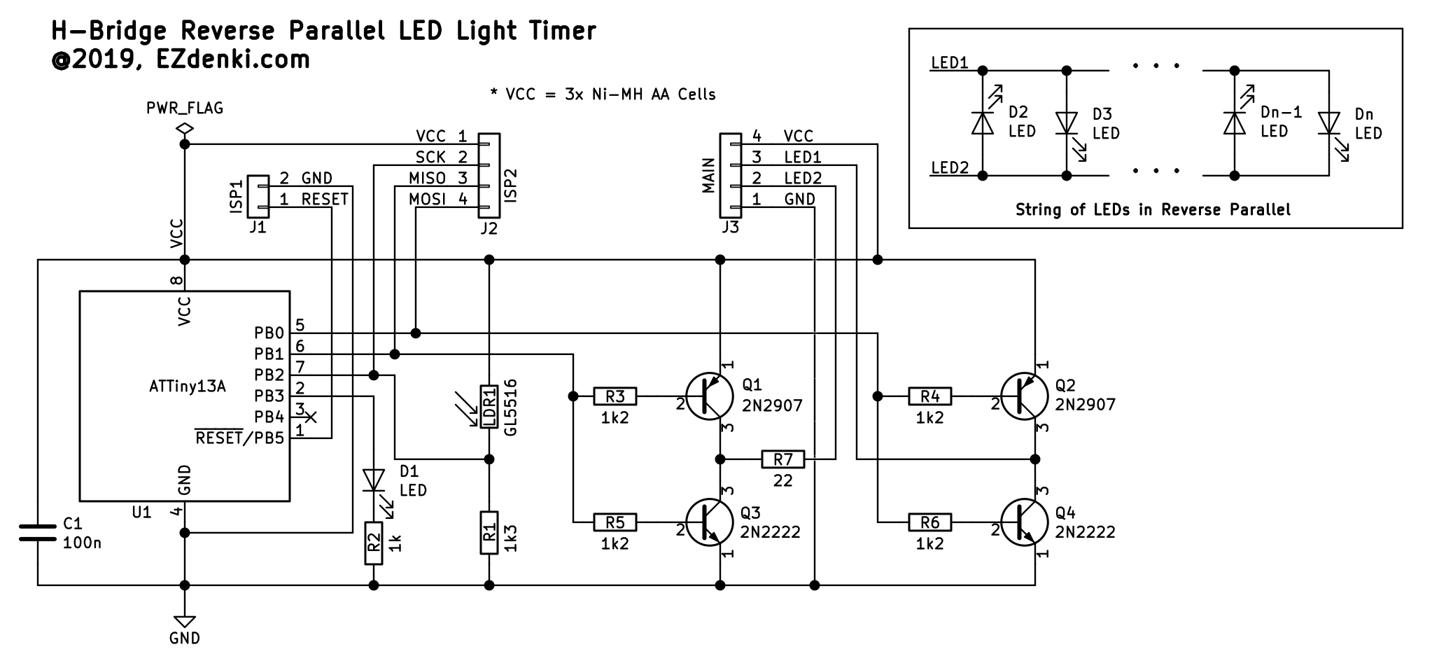
The H-bridge is comprised of 2 pairs of 2N2222 (NPN) and 2N2907 (PNP) transistors. Transistors were used instead of MOSFETs due to the low signal and VCC voltages. This circuit will operate at voltages as low as 2.4 V or whatever the cutoff voltage of the LEDs are.
Pins 5 and 6 of the microcontroller are used to control the H-bridge. When one is high and the other is low, current will flow in one direction through the LED string. When the signals are reversed, current will flow in the opposite direction. When the signal pins are both high or low, no current will flow. So, unlike the case with some H-bridge circuits, there is no danger of unwittingly shorting current to ground through the transistors.
The light sensor is a simple voltage divider comprised of a 1.3 k resistor and the LDR. The resistance of the LDR is inversely proportional to the intensity of the light that hits it. In other words, the brighter the light, the lower the resistance, and the darker the light, the higher the resistance. At night, the resistance will increase, and bring the voltage of the divider down. When it crosses some threshold, the microcontroller will start it's timer and turn on the LED string. The little red LED is an indicator to show that the circuit is operating even when the LED string is not powered. If it's not flashing (and the LED string is not powered), then the batteries are too low to power the circuit and they should be changed. Normally, a regular single flash indicates "DAY" time, a double-flash indicates NIGHT (when the LEDs are off due to spurious light at night) and a triple-flash occurs during "LATE" hours when the LED string is off
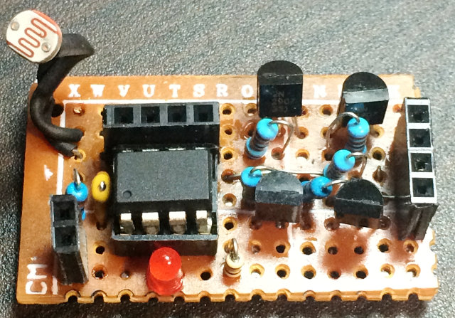
Here is a perfboard layout guide which was drawn up in DIY Layout Creator. The blue wires are under the board and the green wires are jumpers on the top of the board. The 4-pin header above the IC and the 2-pin header at the lower left are for the AVR ISP programming lines.

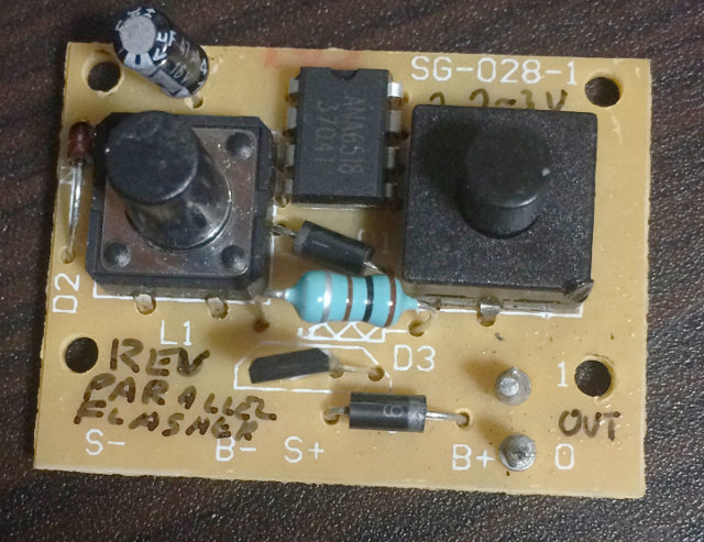
It's somewhat hard to see in this photo, but here is the PCB and AA 3-cell holder tucked neatly into its plastic case. Seems you can get these convenient project boxes from the dollar (100-yen) store, and for some crazy reason they come with a free deck of cards. Go figure.
The code is an attempt at a state machine. Here is a diagram of the basic functionality. While not in the form of the normal connected circles, the program does endlessly travel between these three states so I think it still may qualify. The link opens to a PDF of the state machine diagram.
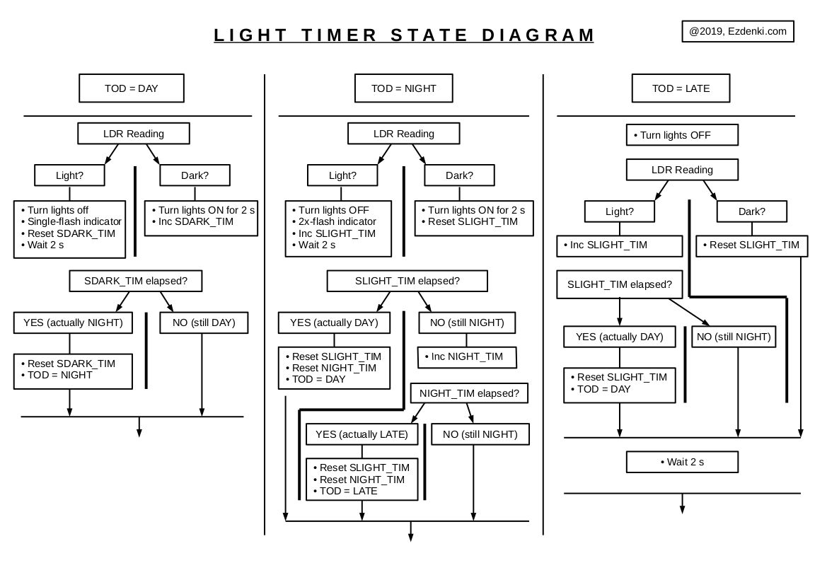
The three main states are DAY, NIGHT, and LATE. Initially a reading of the LDR is made. From that, and based upon the current state, a determination is made as to whether to remain in the current state or change to another state.
Assuming starting in daytime (time of day is "DAY"), the unit will remain in that state until it becomes dark. Once it becomes dark, the state will change to "NIGHT", and the LEDs will turn on and remain on for approx. 4.5 hours. If there is spurious light during that time, the lights will turn off, but the software tries to differentiate between spurioius light and actual sunrise. After 4.5 hours of "NIGHT" the state will change to "LATE" and the lights will be out for the remainder of the night. When sunlight is detected, the state will change to "DAY" and the cycle will repeat.
Here is the code.
Please let me know if this circuit has worked for you!