Signal Generator Based on the AD9850 DDS Module, Rotary Encoder, and LCD Display
Arduino and Standalone AVR-GCC Solutions
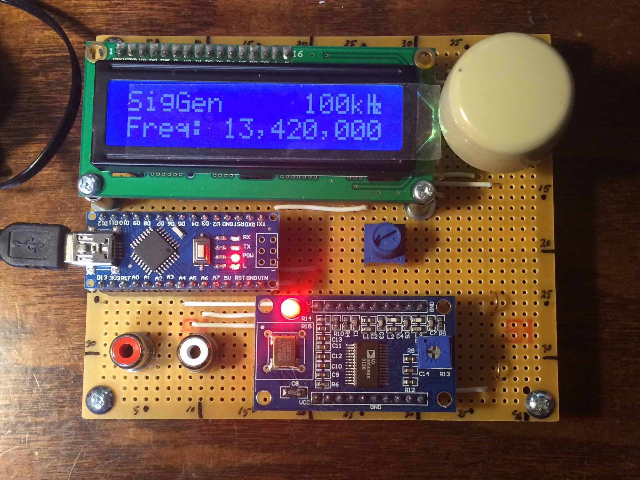
I started out by simply hooking up the module to an Arduino without any other input or output. Using examples found online, it was pretty simple to get the module to output the desired frequencies by changing values in my program. So I decided to make add some real control. For my project I decided I wanted to use a rotary-encoder and LCD for a simple and compact solution. My first attempt was this:
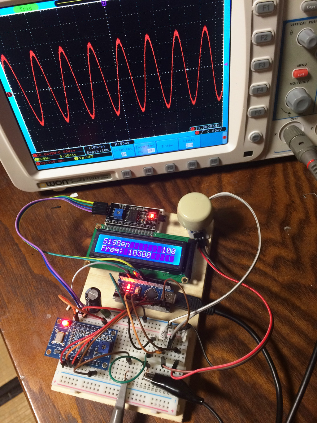
Admittedly, the tricky part of this was getting the encoder to behave. But I think I came up with a good algorithm to deal with it which is responsive to fairly quick turns of the encoder knob. Regarding the above prototype, I used one of those I2C LCD driver boards, seen above the LCD model. I did this partly to reduce the clutter of wires, and partly to try out the board. The board actually works well and even has the contrast control for the LCD built-in. But to lower costs and size, I decided not to use it in later solutions.
The photo at the top of the page is my first hardwired prototype. It uses the arduino code (sketch) below. Note that this code does not use the I2C LCD module, and has some enhanced display functionality. The pin connections between the Arduino and the LCD, DDS module, and the encoder and encoder switch are detailed near the top of the code. Pin references that are just numbers are digital pins. (Those used for the lCD and encoder.) The DDS module connects to analog pins A2, A3, A4, and A5.
Encoder Decoding
The encoder routine was pretty much done from scratch because I wasn't satisfied with most of the overly simple information I found online. The encoder is basically 2 switches with a common ground. If you consider the switching in binary, you get the following sort of movement:Encoder Encoder Combined Combined SW A SW B Binary Decimal 0 0 00₂ 0 Progression for 1 0 10₂ 2 Clockwise Rotation. 1 1 11₂ 3 0 = Indent Position 0 1 01₂ 1 0 0 00₂ 0 Encoder Encoder Combined Combined SW A SW B Binary Decimal 0 0 00₂ 0 Progression for 0 1 01₂ 1 Counter-clockwise 1 1 11₂ 3 Rotation. 1 0 10₂ 2 0 = Indent Positio₂n 0 0 00₂ 0When the encoder is in a detent, both switches are off. Turning ever-so-slightly to the right makes switch-A turn on. Turning a litte more makes both switch-A and switch-B turn on. A little more turn turns off switch-A. And turning just enough to get into the next detent makes both switches off. The opposite pattern is true when turning in a counter-clockwise direction.
I wanted my code to only recognize complete turns from indent to indent and to ignore intermediate input.
1. Start with a zero.
2. At next read, accept either a 2 (clockwise) or a 1 (counter-clockwise).
3. Next, wait for a 3.
4. Next, wait for a 1 if in a clockwise turn or a 2 if in a counter-clockwise turn.
5. Finally, end with a zero.
If at an point the above pattern is broken, or if there is some delay while waiting for the next position before the ending zero, then the routine will exit and wait for the next zero to start fresh.
Here is a back-of-the-large-napkin flow-chart with the progression. I use a variable called CTS and set it to 1 when I'm possibly in the middle of a good read. If at any time something unexpected occurs, I set CTS to 0, which forces the routine to start a fresh read. This means that the routine will ignore all encoder input until the encoder gets back to the detent position, indicated by a zero input.
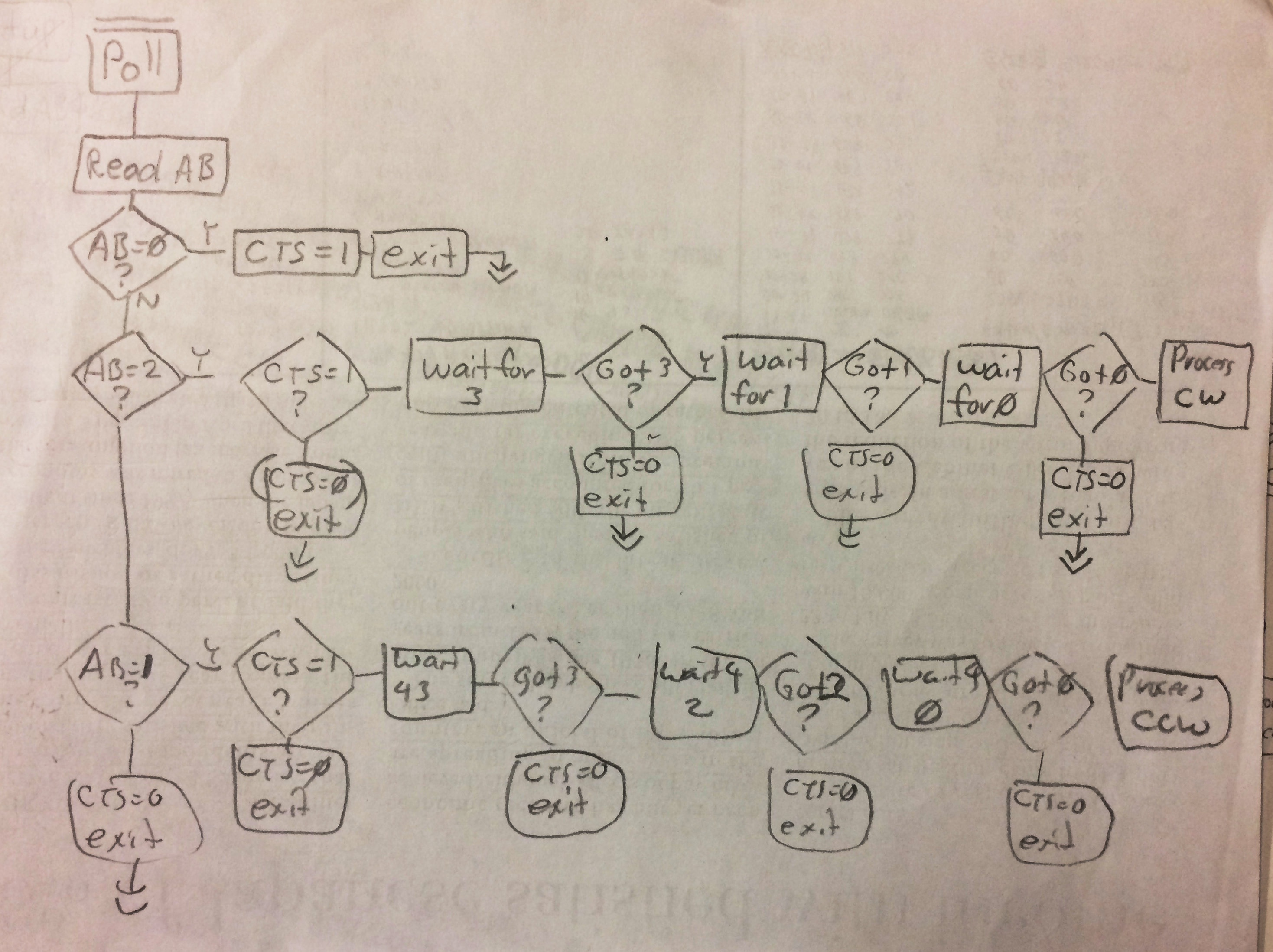
(Click Image to Enlarge)
Running on an ATTiny2313
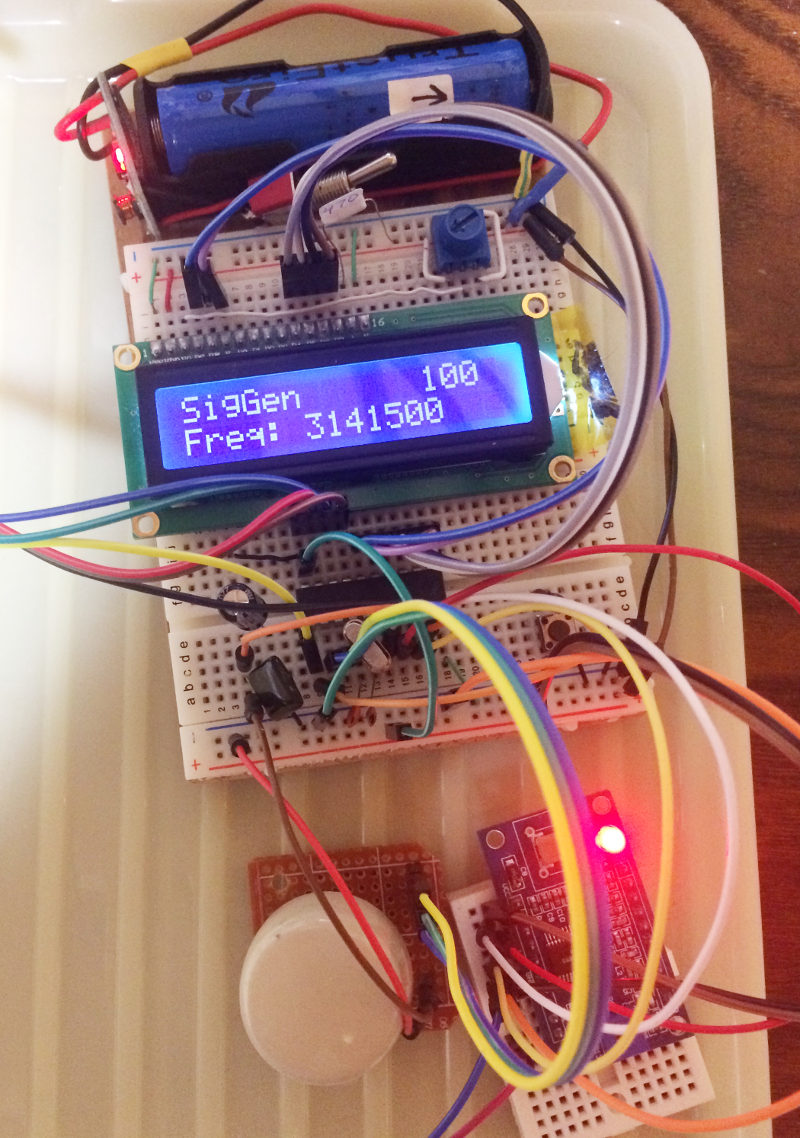
Here is a breadboard setup of the ATTiny2313 version in operation. It's fully functional in that it can use the rotary encoder to select frequencies easily. The "100" in the display is the granularity. Pushing the encoder button decreases the granularity by a factor of 10. After 1, the granularity bumps up to 1 MHz. This allows easy entry of arbitrary frequencies with relatively few pushes and turns.
The ATTiny2313 code is less than 10 bytes shy of the maximum 2048 bytes of code allowed on the 2313. At times I thought that getting this level of functionality in just 2 KB would be impossible. And I realized that I'd have been much better off using another microcontroller from my supply, such as an ATTiny861. But having started the challenge, I couldn't stop until I either realized it was impossible or until I got a working unit. And here is the result! So if you are like me, and have a supply of ATTiny2313s and nothing better, by all means, give it a go!
Here is the schematic.
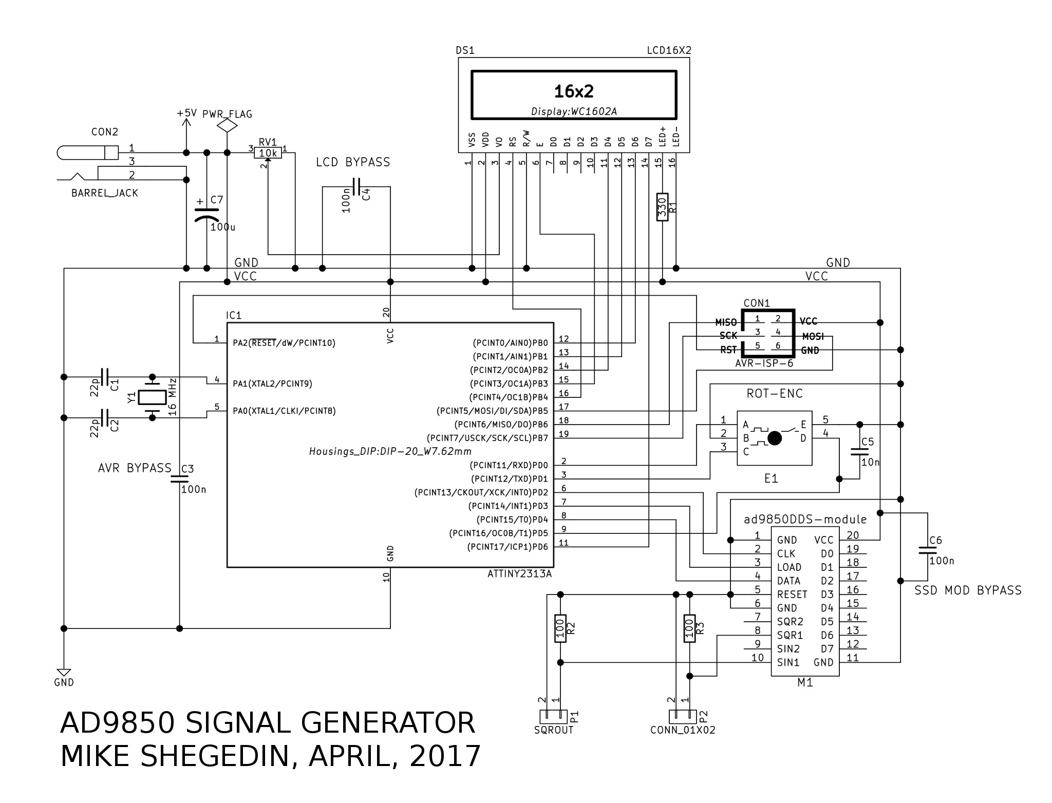
(Click Image to Enlarge)
Notice that the AD9850 DDS module only has 3 pins out to the microcontroller. It turns out that the RESET pin can be tied to ground. That was great news because it means we don't have to share any ISP I/O pins on the ATTiny2313. I found this out later in the game. so the above iterations based on the Arduino Nano use the RESET pin.
And here is the code.
In addition to the normal AVR-GCC toolchain consisting of avr-gcc, make, and avrdude, you will also need the LCD library found at this site:
HD44780 Library for ATMEL.
Not having experience with "make", I started by getting the makefile in the above LCD driver working with my programmer using the included lcd test file. I had to modify it to use my avr programmer and microcontroller. Once I got that going, I modified it again to take on the sig-gen.c program.
Note that there were a couple of lines in the HD44780.c code that generated errors on my Linux system. There were references using backslashes, which will only work on Windows. So if the code won't compile, you might have to go in and fix those.
Top of hd44780.c code
-BEFORE-
/*****************************************************************************
Title  :   HD44780 Library
Author :   SA Development
Version:   1.11
*****************************************************************************/

#include "avr\pgmspace.h"
#include "hd44780.h"
#include "avr\sfr_defs.h"
...
-AFTER-
/*****************************************************************************
Title  :   HD44780 Library
Author :   SA Development
Version:   1.11
*****************************************************************************/

#include "avr/pgmspace.h"
#include "hd44780.h"
#include "avr/sfr_defs.h"
...
You will also have to modify hd44780_settings.h to set the pins, etc to work with your microcontroller. Here is my modified hd44780_settings.h file.
Those who haven't done avr-gcc programming of AVR microcontrollers will likely want some tips on how to get the required toolchain set up. This article will not provide that information. Perhaps at a later date. For those not interested in coding but just want to upload a hex file to an ATTiny2313, here is the hex file:
sig-gen.hex
No PCBs yet. Will post if and when that happens.